How to optimally configure energy storage in off-grid solar systems?
•
How to optimally configure energy storage in off-grid solar systems?
Going off-grid with solar but worried about energy dips? Smart storage configuration is your key to uninterrupted power.
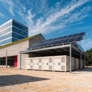
Optimal energy storage in off-grid solar systems requires sizing batteries based on load requirements, depth of discharge limits, and autonomy days while incorporating hybrid technologies like lithium-ion and lead-acid for cost efficiency.
While solar panels capture daylight, it's the storage system that powers your nights. Let's break down how to configure storage that won't leave you in the dark.
For solar grid-connection, how to ensure safety and grid stability?
When your solar system feeds power back to the grid, safety hazards and voltage fluctuations become real concerns.
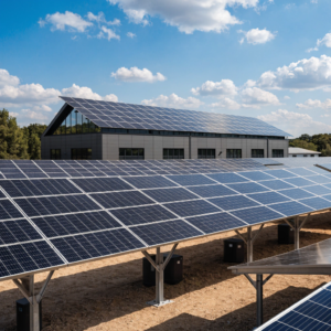
Grid-connected solar systems maintain stability through anti-islanding protection, voltage regulation equipment, and smart inverters that synchronize with utility frequency while meeting IEEE 1547 interconnection standards.
[Grid-tied inverter with safety labels]
Critical Components for Grid Stability
-
Protection Devices
- Anti-islanding relays (detect grid outages in <2 seconds)
- Overvoltage/undervoltage cutoffs (±10% voltage tolerance)
- UL 1741 certified inverters
-
Voltage Regulation Tools Equipment Function Tolerance Smart inverters Adjust VAR output ±3% voltage Step regulators Tap changing ±5% voltage STATCOMs Reactive compensation ±1% voltage -
Communication Protocols
- IEEE 1547-2018 for interconnection
- SunSpec Modbus for inverter monitoring
- DNP3 for utility telemetry
Modern grid-tied systems now incorporate advanced features like ramp rate control to smooth solar variability (max 10%/min change). For urban installations, consider dynamic reactive power support - inverters capable of 0.9 lead/lag power factor. Rural systems may require additional voltage regulators every 3-5km of distribution lines. Always conduct impedance testing before commissioning to verify fault current contribution stays below 15% of grid capacity.
How does long-term PV module aging impact system performance, and how to detect it?
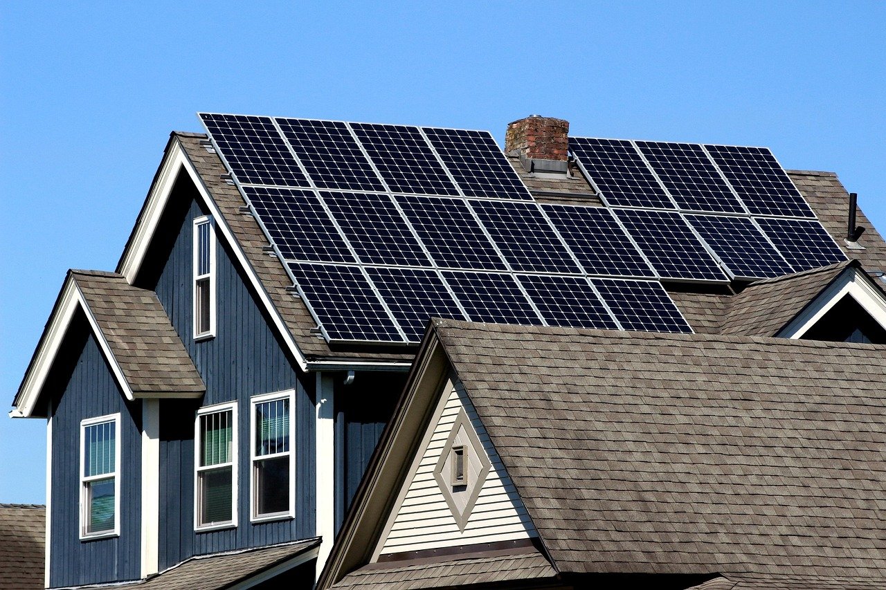
Those pristine solar panels won't stay perfect forever - degradation silently saps your system's strength over decades.
PV modules typically degrade 0.5-1% annually, causing 15-25% power loss over 25 years, detectable through IV curve tracing, infrared thermography, and electroluminescence imaging that reveal microcracks and hot spots.
[Thermal image showing panel hotspots]
Degradation Mechanisms and Detection Methods
Physical Aging Signs:
- Front glass delamination (visible bubbles)
- Backsheet yellowing (UV damage indicator)
- Snail trails (moisture penetration markers)
Performance Testing Tools Comparison:
| Method | Equipment Cost | Detection Capability | Field Applicable |
|---|---|---|---|
| IV Curve Tracer | $$$ | Series resistance ↑ | Yes |
| IR Camera | $$ | Hot cells | Limited |
| EL Tester | $$$$ | Microcracks | No |
| Power Analyzer | $ | General decline | Yes |
For accurate degradation analysis, combine quantitative methods (annual power measurements at STC conditions) with qualitative inspections. Note that light-induced degradation (LID) causes 1-3% initial drop in first 100 hours - don't confuse this with permanent damage. Advanced monitoring systems can track performance ratio (PR) deviations beyond 5% as warning signs. crystalline silicon panels showing >2%/year degradation may qualify for warranty claims - keep meticulous production records.
What technical considerations are needed for protecting solar systems in dusty, salt-spray environments?
Marine and desert installations face particle assaults that can slash solar output by 30% - but strategic protection keeps systems humming.
Dusty/salt-rich environments require corrosion-resistant materials (316 stainless steel, anodized aluminum), tilted mounting (>15°) for self-cleaning, and encapsulated electronics with IP67 protection, coupled with robotic cleaning systems for maintained performance.
[Solar array with cleaning robots in desert]
Harsh Environment Protection Matrix
Material Selection Guide:
| Component | Standard Spec | Harsh Environment Upgrade |
|---|---|---|
| Racking | Galvanized steel | 316 stainless steel |
| Connectors | IP65 | IP68 with dielectric grease |
| Junction Boxes | ABS plastic | Fiberglass reinforced |
| Cabling | XLPE insulation | PTFE with copper-nickel alloy |
Maintenance Protocols:
-
Cleaning Frequency:
- Desert: Every 2 weeks (0.5g/m² dust)
- Coastal: Monthly (salt accumulation checks)
-
Protective Coatings:
- Panel frames: Powder coating + passivation
- Bolts: Xylan or Dacromet treatment
- Trackers: Marine-grade lubricants
In Middle East installations, we've measured 0.8% daily output loss from dust accumulation - automated cleaning systems with deionized water maintain 98% availability. For offshore applications, specify salt mist certification (IEC 61701 Class 2 minimum). Critical detail: use closed-loop cleaning systems in water-scarce regions, and avoid abrasive cleaning tools that scratch anti-reflective coatings. Monitoring system should track soiling losses separately from other degradation factors.
Conclusion
Proper solar system design accounts for storage needs, grid interaction, long-term degradation, and environmental protection - creating resilient renewable energy solutions.